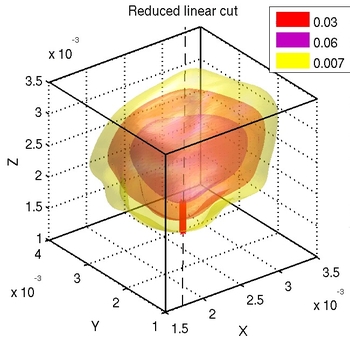
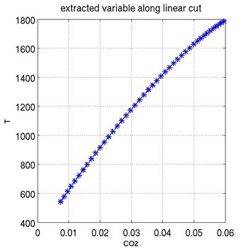
lincut3
algorithm
- draws linear cut normal to flame front between user defined boundaries
- and extracts a 1d profile from the 3d field of a user defined variable along the cut
- plots the cut and variable extracted along the cut


syntax
[XMIN,XMAX,YMIN,YMAX,ZMIN,ZMAX,XX1,YY1,ZZ1,VV1,VV2,VVG]=
 lincut3(X,Y,Z,XS,YS,ZS,NXS,NYS,NZS,fdefine,variable,dl,level,s,iso1,iso2)
example for input
[XMIN,XMAX,YMIN,YMAX,ZMIN,ZMAX,XX1,YY1,ZZ1,VV1,VV2,VVG]=
lincut3(X,Y,Z,0.0022,0.0026,0.0017,0.7683,0.0841,0.6344,CO2,TEMP,0.0001,0.03,'abs',0.06,0.0066)
input arguments
|
X,Y,Z |
vectors defining the rectangular domain |
|
XS,YS,ZS |
coordinates of starting point of the cut |
|
NXS,NYS,NZS |
components of normal vector defining the direction of the cut |
|
dl |
steps between two iterations |
|
fdefine |
variable defining the flame front |
|
variable |
variable to be extracted along the cut |
|
level |
isovalue of fdefine defining the flame front |
|
s |
switch (choose level, iso1,iso2 is rel. or absolut) |
|
iso1, iso2 |
isolevels defining boundaries of flame front |
output arguments
|
XMIN,XMAX,YMIN, |
coordinates of intersection cut – boundaries of flame front |
|
XX1,YY1,ZZ1 |
coordinates of the cut |
|
VV1 |
values of fdefine along the cut |
|
VV2 |
values of variable along the cut |
|
VVG |
gradients of fdefine along the cut |
|
plots |
cut through flame front, |