Multi-Phase Flow
Selected Research Projects
Experimental investigation of flow fields in the interstices of bulk particles with ray tracing based reconstruction
Responsible person: M.Sc. Christin Velten, Dr.-Ing. Katharina Zähringer
Project A1 of the Collaborative Research Centre SFB/TR 287 "BULK-REAKTION".
The flow behaviour of the gas phase in a packed bed has important effects on mass and energy transport processes that are taking place in the bed. It is hence also a central parameter for process optimisation of such systems. Currently, however, only very limited data on the gas flow in packed beds exists, since the access to the particle interstices is very challenging with both probe-based and optical measurement methods. Furthermore, the existing results were typically obtained using refractive index matching, and are hence limited to liquids. For gaseous flows, mainly conclusions obtained using similarity theory are available, which limits the potential range of application.
During the first funding period (FP1) of the Collaborative Research Centre the project developed and validated a novel measurement and reconstruction technique for 2D-flow fields in the gas phase of transparent packed beds that used an innovative combination of Particle Image Velocimetry (PIV) measurements and ray tracing postprocessing of the distorted images. The method delivered directly measured spatio-temporally highly resolved (ms, 100µm), instantaneous mean velocity and turbulence information in the particle interstices and at the surface of transparent glass spheres in body centred cubic model packings (Fig. 1). This also enabled an analysis of turbulence in the interstitial space. Our project thus provided the needed reference for the validation of numerical calculations. The work in FP1 also showed, however, that the required position accuracy for the ray tracing simulations was already highly challenging in the idealized, geometrically regular experimental setups considered so far.
The main emphasis in the second funding period will be on extending the optical measurements to other quantities, such as temperature and dispersion. Also a new experimental configuration will be used that consists of parallel transparent bars arranged in rotatable layers modelling a polyhedral packing (Fig. 2). It will be far less regular than the configuration of FP1, while still providing direct optical access without considerable optical distortion. In cooperation with another project from CRC/TR 287, simultaneous measurements of gas temperature and velocity will be performed using thermographic phosphor particles. Further, laser induced fluorescence (LIF) of Anisole will be used for the determination of gas dispersion in the packed bed. A systematic evaluation of refractive index matching for the use in complex, also moving transparent packed beds will be done on the basis of dimensional analysis to compare results from liquid and gaseous flows. These results will be of particular interest for FP3 when moving beds will be considered. All data sets will be shared with the numerical projects.
| |
|
| Figure 1: Experimental set-up and velocity results from FP1 | Abbildung 2: Experimental set-up and velocity results from FP2 |
Experimental characterization of hydrodynamic and gas-liquid mass transfer in bubble columns
As part of the DFG Priority Program SPP 1740: “Reactive Bubble Flow”
Responsible person: Dr.-Ing. Peter Kovats, Dr.-Ing. Katharina Zähringer
In these projects the velocity fields of liquid and bubbles, as well as their trajectories and size distributions are determined in model bubble columns with optical measurement techniques (Shadowgraphy, PTV, PIV). Mass transfer is measured via laser induced fluorescence (LIF) of fluorescent tracer reactions for oxygen (Fig. 1) and CO2. The results are made available to the scientific community through a data base .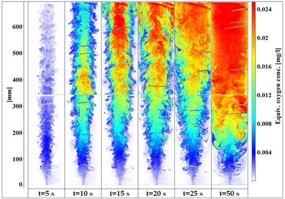
Figure 1: Equivalent oxygen concentration in a bubble chain at different times t.
From the thus obtained data further information can be derived concerning bubble induced mixing, which will be used for model development. The shape information of the bubbles is used to derive models for the bubble eccentricity, which is a key parameter for mass transfer modelling. In order to avoid problems, such as shadows, refraction, etc., induced by the bubbles during optical measurements, 2-tracer-LIF is employed. A non-reactive second tracer is used to monitor with a second camera the light distribution in the liquid. This image is than used as live background for the normalization of the reactive fluorescent dye image (Fig. 2).
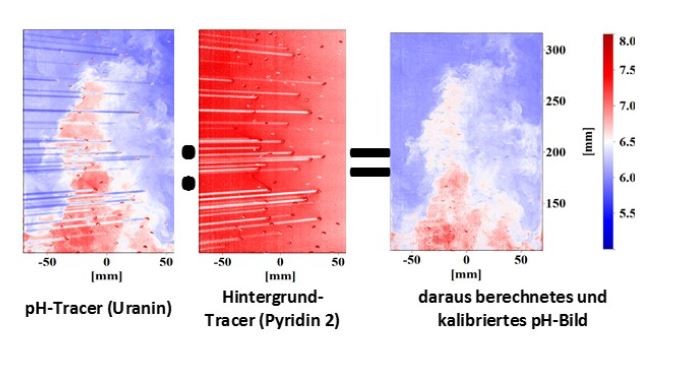
Figure 2: 2-Tracer-LIF for the determination of the pH change, due to CO2 absorption: image of pH-tracer (left), image of live-background (centre) and corrected calibrated pH image.
Experimental Investigation of Wetting Behavior of Solid Materials
Responsible person: Dr.-Ing. Thomas Hagemeier
The objectives are to improve the understanding of wetting processes. Particularly, we want to elucidate the interaction of driving forces (gravity, shear flow or Marangoni-effects) and retention forces (capillary) acting on the fluid and either enhancing or preventing wetting. Major goal is to develop new and optimize existing experimental methods for integrated measurements of decisive parameters. Moreover, we are looking for new modelling concepts to describe dynamic effects of wetting processes (dynamic contact angles). All experiments should account for realistic conditions including surface inhomogeneity.
Example: Wetting with single droplet
Figure: Asymmetrically deformed droplet (fluorescence image, false color corresponding to liquid film thickness, where dark means thin and light mean thick fluid layer) on an inclined plate and corresponding contact line as polar plot
Video: Dynamic droplet contour in a tilting plate experiment; Fluorescence imaging yields 3D-droplet contour (color coding of liquid thickness in [mm]) as well as contact line shape and velocity, while shadow imaging provides the real droplet profile
Lattice Boltzmann simulation of particle-laden flows
Responsible person: Dr. Farshad Gharibi
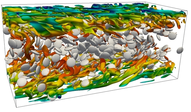
Particle-laden flows are present in many natural and industrial processes including filtration, pollution control, pharmaceutical applications, food industry and fluidized bed reactors. In order to model different particle-laden flows, the in-house lattice Boltzmann solver of the LSS group (ALBORZ) is developed and successfully applied to laminar and turbulent flows with different types of particles. In the four-way coupled simulations, the interaction of particles and the fluid as well as particle-particle and particle-wall interactions are taken into account. Below figure shows a suspension of resolved disk-like particles in a turbulent channel flow at volume fraction of 5%. Vortical structures are illustrated where particles generate small vortices. These particles are found to be able to reduce the drag at sufficiently high volume fractions due to being aligned parallel to the wall.
Experimental Investigation of Two-Phase Air-Water Flows in Centrifugal Pumps
Responsible person: Dr.-Ing. Michael Mansour
Due to their simplicity and extreme flexibility, centrifugal pumps are used very commonly in many domestic and industrial applications. When transporting a single-phase flow, centrifugal pumps show excellent performance. Nevertheless, significant performance deterioration occurs, while transporting two-phase gas-liquid mixtures. A remarkable drop in pump parameters can be seen even at very low gas volume fractions (lower than 1%). This problem is highly relevant for several engineering and industrial fields. The main issue is that the gas phase has a strong and rapid tendency for accumulation on the impeller blades, leading to a phenomenon called “gas-locking”, which prevents an efficient energy transfer to the transported medium. Moreover, strong flow instabilities and intense system vibrations can be generated due to the continuous formation and discharging of huge gas pockets. This phenomenon is known as “surging”. In the present experiments, the pump performance is investigated considering different impellers (i.e., closed and semi-open impellers), tip clearance gaps, rotational speeds to obtain the optimal operating zones of the pump. The effect of inducers is considered as well.
Modeling and Dynamic Simulation of Multi-Step Particle Cross-Flow Separation in Turbulent Fluid Flow
Responsible persons: M.Sc. Eduard Lukas, Dipl.-Ing. Christoph Roloff
The multi-step particle cross-flow separation in turbulent airflow (wind sifting) is a typical separation process for the separation of a large number of raw materials, waste, intermediate and byproducts in many branches of the material conversion industry and therefor an ideal sample process within the priority program, which aims for the development and supply of tools for a dynamic simulation of cross-linked processes involving solids. Within this sub-project, the process is characterized using the example of a zig-zag sifter by means of modern experimental methods (PIV, PTV, LDV, Shadowgraphy) and multi-phase flow simulations (CFD-DPM, CFD-DEM). From this, parameters for a simplified, dynamic apparatus model can be derived and the implementation into the flow sheet simulation can be accomplished.
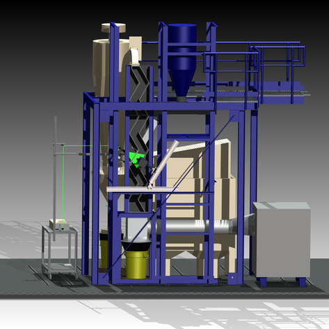
Figure: Zig-zag sifter pilot plant with PIV technology installed
Dynamic Simulation of a Liquid-Solid Crystallizer via CFD-DEM
Responsible person: Dr.-Ing. Kristin Kerst
The DEM (Discrete Element Method) is a promising Method to describe and therefore simulate the interactions of solid crystals in continuous crystallizers. Coupled with Computational Fluid Dynamics (CFD), it provides an opportunity for a detailed description of the crystal particles’ fluidization behavior. The simulation is, however, computationally intense and thus a compromise between physically simulated process time and the number of simulated particles must be found. Optical validation experiments by means of Shadowgraphy are being carried out to accompany the simulations. Experiments on the real-life crystallization process are available through Prof. Andreas Seidel-Morgenstern’s research group at the Max Planck Institute Magdeburg.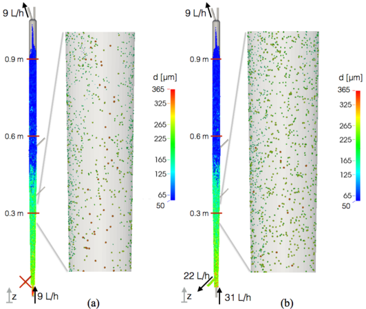
Figure: CFD-DEM simulation of fluidized asparagine monohydrate crystals in the crystallizer
Optimal Reactor Design and Operation for Liquid Multiphase Systems
Responsible person: Dr.-Ing. Peter Kovats, Dr.-Ing. Katharina Zähringer, Dr.-Ing. Michael Mansour
Sub-project B1 of the Collaborative Research Centre SFB/TRR 63 “Integrated Chemical Processes in Liquid Multi-Phase Systems” (InPROMPT), in collaboration with the research group of Prof. Sundmacher at the MPI, Magdeburg. In course of the research project: Characterization of liquid propagation (as thin liquid film, rivulet or individual droplet) on complex solid surfaces with different wetting properties (hydrophilic to hydrophobic).
After the development of a model-based methodology for the optimal reactor design for gas/liquid systems by the MPI and its use for a concept of an optimal continuous reactor for the Rh-catalyzed hydroformylation of 1-dodecene to tridecanal in a thermomorphic solvent system (TMS), the sub-project’s goal was now to characterize the necessary reactors. Their behaviour is studied from a reaction engineering and transport physics point of view under variation of all essential structural and operational parameters.
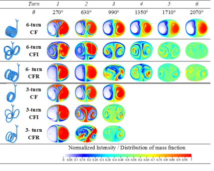
To this end, velocity field measurements via PIV and tomo-PIV are carried out on various model reactors (stirred-tank reactor, Fig 1, helical tube reactor, Fig. 3), also under reaction conditions (10 bar, ca. 90 °C, organic solvents, Fig. 1). Simultaneously, mixing (Fig.2) and mass transfer are characterized in the system by means of fluorescent tracer reactions and laser induced fluorescence (LIF).
The experimental and numerical results show the considerably better mixing and mass transfer in helically coiled reactors, which is due to the secondary Dean vortices. An early flow redirection after maximum three turns of the helix, like it is done in Coiled Flow Inverters or Coiled Flow Reversers, has been proved to be particularly beneficial.
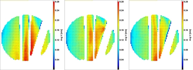
Abbildung 1: Comparison of experimentally determined average velocities in a stirred tank reactor with water (left), and two different TMS systems (center and right) at a pressure of 9 bar.
 |
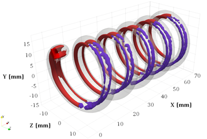 |
| Figure 2: Mass fraction of two miscible liquids in the cross-sections of different helically coiled reactors at Re=500. | Figure 3: Dean vortices, visualized by the 3D Q-Criterion in a helical reactor at Re = 220 and De = 89: time-averaged 3D PIV measurements (purple isosurfaces) and numerical simulation (red isosurfaces). |
Related links: Reactive Flow
Dispersion and Coalescence in Stirred Micellar Three-Phase Systems
As part of the DFG Special Research Area/Transregio TRR 63 “Integrated Chemical Processes in Liquid Multi-Phase Systems”
Responsible person: M.Sc. Anurag Misra, Dr.-Ing. Katharina Zähringer
Substituting organic basic chemicals by renewable raw materials is essential for the chemical industry due to ever more limited and expensive raw materials. The SFB TR 63 aims to optimize reactions in multi-phase systems in order to enable the efficient manufacturing of basic chemicals. Within the sub-project, our colleagues in Berlin are investigating the coalescence of oil droplets in aqueous solution using an endoscope. This measurement data is used as a starting point by the department’s staff for the CFD simulation of coalescence with population balances in ANSYS Fluent. Various geometries, a stirred tank and a decanter, are employed. In addition to modeling the coalescence behavior, the phase separation is also being investigated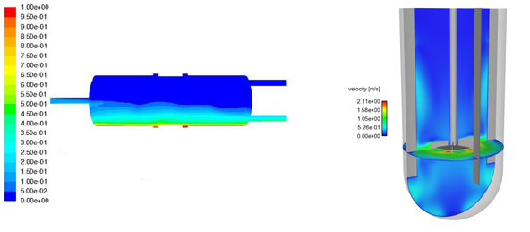
Figure: left: volume fraction for the second phase in the decanter after 500s, right: velocity contour in the stirred tank reactor.
Multi-objective optimization of high-pressure gasoline injector nozzles using Genetic Algorithms
Responsible person: Dr.-Ing. Robin Hellmann
Die Geometrie eines Hochdruck-Einspritzventils ist eine Schlüsselkomponente, um eine optimale Verbrennung mit minimalen Emissionen und höchstmöglichem Wirkungsgrad zu erreichen. Neue Emissionsvorschriften erfordern ein tiefgreifendes Verständnis der primären Strahleigenschaften wie z.B. Flugbahn, Aufbruchswinkel, Zerstäubung und Eindringtiefe. Diese Strahleigenschaften werden bei modernen Mehrloch-Hochdruck-Benzininjektoren stark von der Ventilsitzgeometrie beeinflusst.
Wird der große, fertigbare Geometrieraum eines typischen Ventilsitzes ausgenutzt, können optimale Lösungen für die motorspezifischen Anforderungen erzielt werden. Dazu wird ein Eulerscher 3D-CFD-Innenströmungs-Simulationsprozess mit einer Lagrangeschen 3D-CFD-Spraysimulation unter Verwendung der „Discrete Droplet-Method“ (DDM) gekoppelt. Die Implementierung dieser beiden Simulationsansätze in die Software „OPtimization Algorithm Library ++“ (OPAL ++) ermöglicht neben der vollständigen Automatisierung und hohen Effizienz eine systematische Untersuchung des Geometrieraums unter Berücksichtigung geometrischer Einschränkungen. Für eine festgelegte Strahlrichtung und Durchflussrate werden sowohl die Penetration als auch der Spraykegelwinkel mithilfe eines genetischen Algorithmus minimiert.
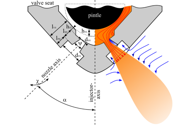
Figure: Schematic representation of a high-pressure injector including the varied geometry parameters
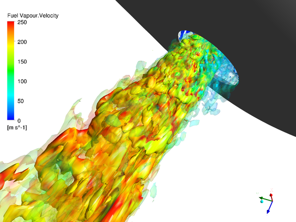
Figure: Highly resolved LES-simulation to validate the simulation settings used for optimization
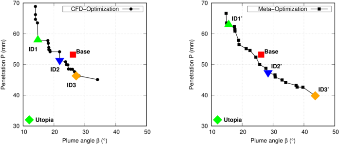
Figure: Pareto-front of the 20th generation shows significantly improved spray characteristics compared to a basic geometry
Simulation of a Multi-Phase Stirred Tank Crystallization
in collaboration with “Research Group Physical and Chemical Foundations of Process Engineering (PCF) at the MPI Magdeburg”
Responsible person: Dr.-Ing. Luis Medeiros de Souza
The exact description of multi-phase chemical reactors requires various layers of modeling, e.g., fluid dynamics, population balances, growth kinetics. This work couples the Euler-Euler Method with Quadrature Method of Moments (QMOM). Nevertheless, pure 3D simulations lead to reasonable computing times. Motivated by this, a methodology was developed that combines the 3D and the 0D simulation. This developed methodology considers the detailed description of the crystal growth.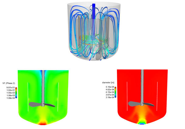
Figure: above: flow lines in a stirred tank reactor, left: disperse phase volume fraction, right: Sauter mean diameter of the disperse phase.
Direct Numerical Simulation of the Combustion of n-Heptane in a Turbulent Jet
As part of the DFG Research Group FOR 1447: “Physicochemical-based models for the prediction of safety-relevant ignition processes”
Responsible person: Dr.-Ing. Abouelmagd Abdelsamie
See also: http://www.for1447.ptb.de/for1447/213.html
This work investigates the evaporation and self-combustion of sprays in turbulent jets via Direct Numerical Simulation (DNS). Specifically, the effects of shear stress on evaporation and self-combustion mechanisms of sprays are quantified and illustrated. The interactions between droplets, turbulence, and the flame are investigated by looking at the topology of the reaction fronts, for which the fundamental characterization is determined by mixing fraction, scalar rate of dissipation, flame index, as well as distribution of temperature and heat transfer. The influence of local equivalence ratios and droplet diameter is investigated by varying these two parameters.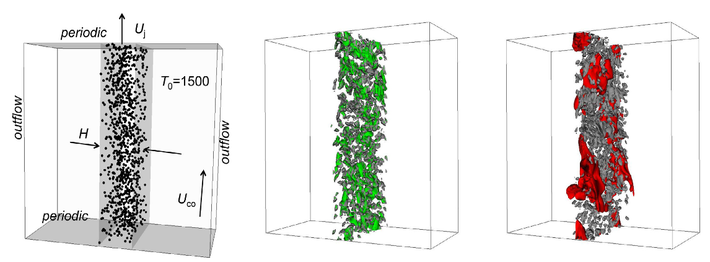
Figure: Spray evaporation and turbulent combustion. Left: schematic representation of the configuration considered. Middle: Isosurfaces of the mass fraction (0.015) of n-heptane in the gas phase at a temperature of 1106 K at a time of t = 5 Tj represented in grey or green, respectively. Right: Isosurfaces of the mass fraction (0.0174) of n-heptane in the gas phase at a temperature of 1800 K at a time of t = 11 Tj represented in grey or red, respectively.
Experimental Characterization of the Gas-Liquid Flow in a Horizontal Channel with a Variable Cross-Section
Responsible person: Dr.-Ing. Michael Mansour
Two-phase flow with gas bubbles or gas pockets can be found in various processes with environmental, chemical, or process engineering background. The complexity of such flows results from the coupled combination of the gas and liquid phase and the requirement for sufficient resolution. Using experimental and numerical methods, the project follows the characterization of the flow structures while passing through a horizontally arranged channel with a divergent cross-section. In essence, the interaction of the gas and liquid phase, as in phenomena such as bubble collision and coalescence, is to be studied.
Figure: Streamlines derived from LDA measurements of the horizontal channel with divergent section conducted at the experimental plant
Numerical Investigations of a Gravitation Water Vortex Power Plant as a Fish Ladder
Responsible person: Dr.-Ing. Nils Lichtenberg, Dr.-Ing. Stefan Hörner
The requirements for good water quality in Europe’s bodies of water also mean restoring the ecosystem and therefore allowing fish to freely migrate upstream and downstream. As a consequence, measures that are taken and structures that are built must allow for such migration. This project deals with the resulting geometric and hydraulic requirements for such structures. Based on simulation results, the suitability of a gravitation water vortex power plant as a fish ladder is underlined, since all the requirements for flow velocity are maintained.

Figure: left: schematic representation of the gravitation water vortex power plant, right: velocity profile with representation of the mesh refinement in areas with large velocity gradients and the free surface


