Reactive Flow
Selected Research Projects
Lattice Boltzmann method for reactive flows
Responsible person: Dr.-Ing. Seyed Ali Hosseini, M.Sc. Tanya Neeraj
The Lattice Boltzmann method, being an efficient alternative to classical CFD tools, can be extended to more complex flows, namely multi-species reacting flows. To that end, our in-house LB solver, ALBORZ, has been equipped with models, on top of the classical isothermal lattice Boltzmann formulation, to simulate thermal flows in heterogeneous media -i.e. with variable diffusion coefficients and heat capacities such as porous media, and incompressible/thermos-compressible multi-species reacting flows. A plethora of models for species diffusion, from the very simple generalized Fick approximation to the Maxwell-Stefan equation for multi-component flows are available. Apart from the previously mentioned models, ALBORZ also includes a diffuse interface solver -phase-field, for multi-phase problems. These models are currently being used in a multitude of application areas, such as medical flows, combustion, crystallization or reacting flows in packed beds.
Figure 1: Instantaneous velocity field in channel flow with heated obstacle at Re=3854 (based on the obstacle size).
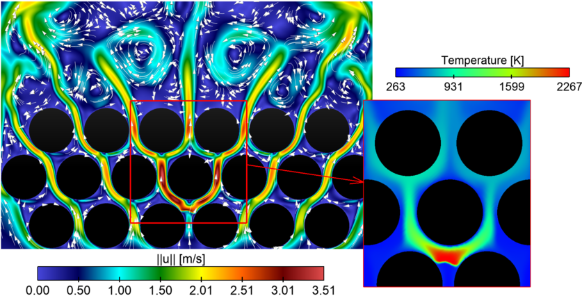
Figure 2: Premixed flame interacting with isothermal cylinders.
Characterisation of the laminar-turbulent transition in coiled (helical) reactors
Responsible person: M.Sc. Conrad Müller, Dr.-Ing. Katharina Zähringer
Compact systems that very quickly lead to excellent homogenisation of momentum, temperature and concentration fields are indispensable for countless applications in process and energy technology. A robust and maintenance-free solution is always preferable, so that the use of moving parts (e.g. stirrers) should be avoided as far as possible. Static mixers can be used as an alternative. However, these lead to very high pressure losses and correspondingly high process costs.
The main objective of the project is to gain a better understanding of the laminar, transient and turbulent gas-liquid flow conditions in spiral reactors and their influence on mass transfer and homogenisation. Particular emphasis will be placed on investigating the structures in the liquid plug that are responsible for gas-liquid mass transfer and mixing. The positive influence of additional flow deflection on mixing, mass and heat transfer, as has already been established in coiled-flow inverters and coiled-flow reversers, is to be clarified by detailed investigation of the 3-dimensional flow field. In the transient range, additional secondary flow structures certainly also play an important role, the occurrence and stability of which are to be investigated. On this basis, it should be possible at the end of the project to analyse and demonstrate the relationship between the geometry of the spiral reactor, process conditions and homogenisation or mass transfer with the help of relevant dimensionless numbers.
 |
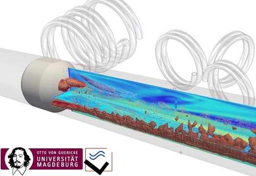 |
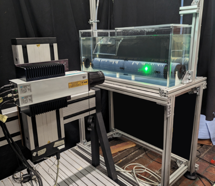
| Fig. 1: Experimental set-up for Laser-Doppler-Anemometry measurements in a helical reactor. | Fig. 2: Velocity and vorticity measurements in a helical reactor. |
Experimental characterization of hydrodynamic and gas-liquid mass transfer in bubble columns
As part of the DFG Priority Program SPP 1740: “Reactive Bubble Flow”
Responsible person: Dr.-Ing. Peter Kovats, Dr.-Ing. Katharina Zähringer
In these projects the velocity fields of liquid and bubbles, as well as their trajectories and size distributions are determined in model bubble columns with optical measurement techniques (Shadowgraphy, PTV, PIV). Mass transfer is measured via laser induced fluorescence (LIF) of fluorescent tracer reactions for oxygen (Fig. 1) and CO2. The results are made available to the scientific community through a data base .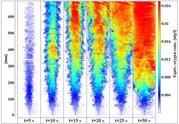
Figure 1: Equivalent oxygen concentration in a bubble chain at different times t.
From the thus obtained data further information can be derived concerning bubble induced mixing, which will be used for model development. The shape information of the bubbles is used to derive models for the bubble eccentricity, which is a key parameter for mass transfer modelling. In order to avoid problems, such as shadows, refraction, etc., induced by the bubbles during optical measurements, 2-tracer-LIF is employed. A non-reactive second tracer is used to monitor with a second camera the light distribution in the liquid. This image is than used as live background for the normalization of the reactive fluorescent dye image (Fig. 2).
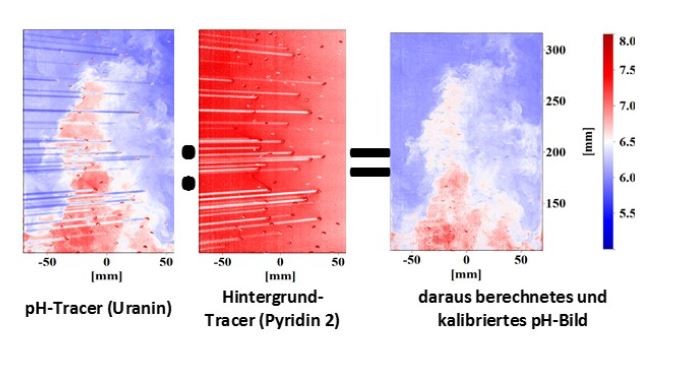
Figure 2: 2-Tracer-LIF for the determination of the pH change, due to CO2 absorption: image of pH-tracer (left), image of live-background (centre) and corrected calibrated pH image.
Related links: Multi-Phase Flow
DNS of turbulent Flames
Responsible persons: Dr.-Ing. Abouelmagd Abdelsamie, Dr.-Ing. Cheng Chi
Direct Numerical Simulation (DNS) is currently the most exact numerical tool in investigating turbulent flame structure. DNS allows for the resolution of very fine turbulent flow structures, and the detailed description of heat transfer and chemical reactions. Over the course of 20 years, three DNS solvers were developed: PARCOMB, p3, and DINO. DINO represents the newest generation of DNS solvers. It relies on a low Mach approach in the simulation of turbulent, reactive, and two-phase problems. DINO uses 6th-order central finite differences for the spatial discretization, whereas varying temporal integration techniques are employed: 4th-order explicit Runge-Kutta method, 3rd-order half-implicit Runge-Kutta method, and an implicit Radau5 integrator. Physical, thermal, and transport properties, as well as chemical kinetics are calculated in DINA with Cantera 1.8 and/or Eglib 3.4. DINO can be used on various clusters and super computers: fig. 1, for example, shows the scaling curve for DINO simulations with turbulent, reactive flow: (1) a time-evolving jet, (2) spherical flame, (3) a spatially evolving jet.
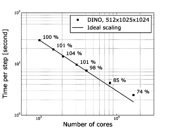
Figure: DINO parallel scaling on the SuperMUC supercomputer
Animation: Temperature isosurface of a time-evolving jet of a reactive ethylene/air mixture.
Animation: Temperature isosurface a spherical flame of a reactive synthesis gas/air mixture.
Animation: Isosurface heat release (red), Q-criterion (white) and 2D surface temperature of a spatially evolving jet of a hydrogen/air mixture
Optimal Reactor Design and Operation for Liquid Multiphase Systems
Responsible person: Dr.-Ing. Peter Kovats, Dr.-Ing. Katharina Zähringer, Dr.-Ing. Michael Mansour
Sub-project B1 of the Collaborative Research Centre SFB/TRR 63 “Integrated Chemical Processes in Liquid Multi-Phase Systems” (InPROMPT), in collaboration with the research group of Prof. Sundmacher at the MPI, Magdeburg.
After the development of a model-based methodology for the optimal reactor design for gas/liquid systems by the MPI and its use for a concept of an optimal continuous reactor for the Rh-catalyzed hydroformylation of 1-dodecene to tridecanal in a thermomorphic solvent system (TMS), the sub-project’s goal was now to characterize the necessary reactors. Their behaviour is studied from a reaction engineering and transport physics point of view under variation of all essential structural and operational parameters.
To this end, velocity field measurements via PIV and tomo-PIV are carried out on various model reactors (stirred-tank reactor, Fig 1, helical tube reactor, Fig. 3), also under reaction conditions (10 bar, ca. 90 °C, organic solvents, Fig. 1). Simultaneously, mixing (Fig.2) and mass transfer are characterized in the system by means of fluorescent tracer reactions and laser induced fluorescence (LIF).
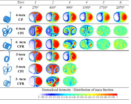
The experimental and numerical results show the considerably better mixing and mass transfer in helically coiled reactors, which is due to the secondary Dean vortices. An early flow redirection after maximum three turns of the helix, like it is done in Coiled Flow Inverters or Coiled Flow Reversers, has been proved to be particularly beneficial.
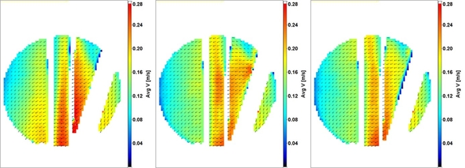
Figure 1: Comparison of experimentally determined average velocities in a stirred tank reactor with water (left), and two different TMS systems (center and right) at a pressure of 9 bar.
 |
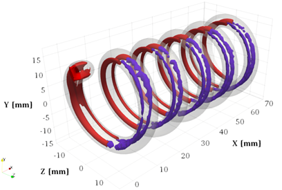 |
| Figure 2: Mass fraction of two miscible liquids in the cross-sections of different helically coiled reactors at Re=500. | Figure 3: Dean vortices, visualized by the 3D Q-Criterion in a helical reactor at Re = 220 and De = 89: time-averaged 3D PIV measurements (purple isosurfaces) and numerical simulation (red isosurfaces). |
Related links: Multi-Phase Flow
DNS of Spray-Flames
Responsible person: Dr.-Ing. Abouelmagd Abdelsamie
A detailed description of reactive spray flows is associated with major challenges. Using Direct Numerical Simulation (DNS), the details of the complex physical and chemical processes of spray combustion can be detected. However, this is associated with a very high expenditure of computation time. The main objectives in this area are to investigate spray evaporation and auto-ignition in turbulent flows under the influence of shear stress. The interactions between droplets, turbulence, and flame structure can be determined by examining the topology of the reaction fronts, which are characterized by mixing ratios, scalar dissipation, flame index, as well as temperature and heat release. All subsequent simulation results were obtained with our program, DINO, and n-heptane as a fuel.
Animation: Spray in homogeneous, isotropic turbulence: blue isosurface of n-heptane concentration in the hot gas mixture (air); yellow spheres with black arrows show the liquid n-heptane droplets with their velocity vectors; 2D sections show the temperature of the gas mixture.
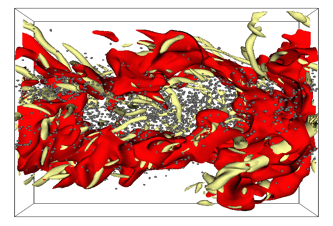
Abbildung: Spray in a time-evolving jet: red isosurfaces show temperatures of 1800 K; yellow isosurfaces correspond to the Q-criterion showing the coherent turbulent structure; gray spheres represent the enlarged droplet size for better visibility.
Animation: Spray injection into hot air: 2D sections show the gas temperature; Spheres correspond to the droplets.
Detailed Chemical and Harmful Substance Simulations
Responsible persons: Dr.-Ing. Abouelmagd Abdelsamie, Dr.-Ing. Cheng Chi, apl. Prof. Gábor Janiga
The largest share of energy production worldwide is based on combustion. A thorough understanding of these processes is of high interest in order to optimize existing plants for greater efficiency while reducing the production of harmful substances. Numerical simulations can be of great benefit in this effort. Here, Direct Numerical Simulation (DNS) is the only way to investigate the complex physicochemical and turbulent interactions as precisely as possible. Such simulations require an extremely high computational complexity, since separate transport equations are used for each species. Therefore, simplified chemical models (FPI/FGM) have been integrated into our newest DNS tool, DINO, while the detailed description of the flow is maintained. This simplification reduces the high number of required transport equations and thus the computational complexity. The quality of the simplified chemical model is tested by comparison to detailed simulations for academic and practical turbulent applications.
The following animation shows DNS results in an ethylene/air flow. The reduced chemical model (FPI) shows an excellent agreement with the detailed chemistry for low-turbulent applications. This simplified chemistry is 10 times faster than a simulation with detailed chemistry (32 species, 206 reactions).
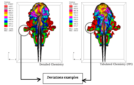
Laminar reactive flows can also be found in many industrial applications, for example, household burners. A modeling of such problems is also of great interest for the further optimization of these applications. For this, the open source tool OpenFOAM has been extended to the description of laminar combustion with detailed chemistry and multi-species transport.
Chemical Reaction in a Static Mixer
Responsible person: Dr.-Ing. Katharina Zähringer
Sub-project “Numerical Simulation of Static Flow Mixer with Experimental Validation” of the SPP 1141 “Analysis, Modeling, and Calculation of Flow Mixers with and without Chemical Reactions” http://gepris.dfg.de/gepris/projekt/5471746
Static mixers are tubes or channels with fixed baffles to mix fluids. The energy derived from the fluid flow is used for mixing. The static mixer used here with teethed ridges (figure 1) is similar to the commercial mixer of the SMX type (figure 2) for homogenizing and suspending.
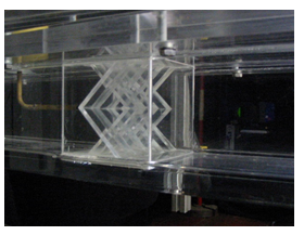
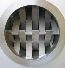
Figure 1 Figure 2
During laminar mixing, widely varying local concentrations occur behind the mixer, which can be visualized by means of appropriate indicators (fluorescent dyes) - but only on the macromixing or mesomixing "level".
The main objective of the project's experimental studies, therefore, was the validation and development of measurement methods, which would also experimentally portray micromixing. The results obtained can then serve as a basis for the validation of numerical tools.
To visualize micromixing, a chemical reaction between the fluids to be mixed can be used, since the reaction requires mixing at the molecular level. A mixture of two fluorescent dyes should ideally be employed. One dye is inert and serves as an indicator for macromixing. The second dye changes its fluorescent properties (change in emission wave length and, perhaps enhancement in fluorescence intensity) due to a chemical reaction with certain ions and serves as a micromixing indicator. The concentration fields of inert and reactive dye can be measured simultaneously.
A neutralization reaction can be used here, the course of which can be observed by a fluorescent pH indicator. In particular, fluorescein is especially fitting, since it is inexpensive, and possesses a strong fluorescence and a high quantum yield (93%).
In combination with an inert dye (e.g., pyridine 2), micromixing and macromixing can be recorded simultaneously (figure 3).
pyridin 2 concentration pH measured with uranine
Figure 3: Simultaneous measurement of macromixing (left) and micromixing (right)
Plasma-Assisted Combustion
Responsible person: Dr.-Ing. Katharina Zähringer
in collaboration with the Univ. of Stuttgart Research Group Prof. Riedel, and HMTI Minsk
Health problems caused by emissions lead to a tightening of tolerable standards for combustion systems. The methods used today, which are based on a better control of the operating point in the combustion chamber or on a subsequent catalytic purification, are efficient, but continue to reach their limits. One of the alternatives is the use of electronically excited species during combustion. This aims to change the performance and directly reduce emissions or, in a second stage, decompose pollutants and render them harmless. These issues have been investigated in detail both experimentally as well as numerically in the context of this project.
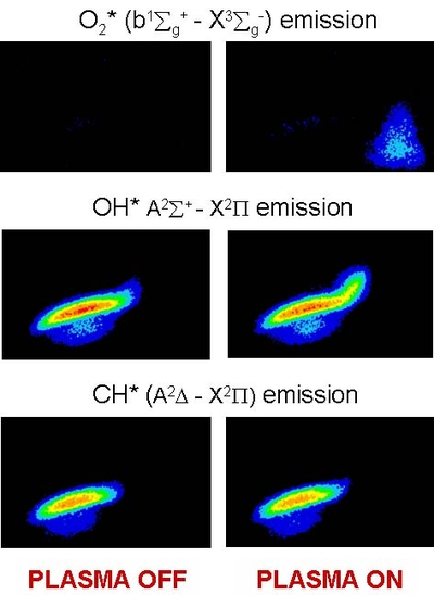
Figure: Influence of the plasma on the flame
Optical Measurement Methods in Combustion Research
Responsible person: Dr.-Ing. Katharina Zähringer
Experimental investigations of flame structure are important in terms of a better understanding of pollutant formation and flame stabilization. They also assist in a better understanding of turbulent combustion and modeling as well as the validation of numerical programs and procedures.
Investigations in this area relate to, for example, the determination of the CH radical by laser-induced fluorescence. The CH radical marks the flame front and is consequently often used in studies pertaining to flame stabilization. It also plays an important role in the formation of prompt NO. The CH concentration was determined by LIF, for example, in a premixed and non-premixed counterflow flat flame in various configurations.
Im Rahmen des DFG-Sonderforschungsbereich/Transregio TRR 63 „Integrierte chemische Prozesse in flüssigen Mehrphasensystemen" (InPROMPT), in Zusammenarbeit mit der Arbeitsgruppe Prof. Sundmacher am MPI, Magdeburg.
Verantwortlich: Dr.-Ing. Peter Kovats, Dr.-Ing. Katharina Zähringer, Dr.-Ing. Michael Mansour
Siehe auch: http://www.inprompt.tu-berlin.de
Nachdem zunächst durch das MPI eine modellgestützte Methodik für den optimalen Reaktorentwurf für Gas/flüssig-Systeme unter Betrachtung ideal durchmischter Fluidballen entwickelt und ein Konzept für einen optimalen kontinuierlichen Reaktor für die Rh-katalysierte Hydroformylierung von 1-Dodecen zu Tridecanal in einem thermomorphen Lösungsmittelsystem (TMS) abgeleitet worden war, besteht das Ziel dieses Teilprojekts nun darin, die dafür benötigten Reaktoren zu charakterisieren. Das Reaktorverhalten wird dabei reaktionstechnisch bzw. transportphysikalisch unter Variation aller wesentlichen Struktur- und Betriebsparameter untersucht.
Hierzu erfolgen an verschiedenen Modellreaktoren (Rührreaktor Abb.1, Wendelreaktor Abb.3) Messungen der Geschwindigkeitsfelder mittels PIV und Tomo-PIV, auch unter Reaktionsbedingungen (10 bar, ca. 90°C, organische Lösungsmittel, Abb.1). Simultan dazu wird das Mischverhalten (Abb.2) und der Stoffübergang im System mittels fluoreszierender Indikatorreaktionen und laser-induzierter Fluoreszenz (LIF) charakterisiert.
Die experimentellen und numerischen Ergebnisse zeigen die deutlich verbesserte Mischung und Stoffübergang in den Helixreaktoren, die durch die Sekundärströmung mit Dean-Wirbeln hervorgerufen wird. Eine frühzeitige Umlenkung der Strömung nach einer bis maximal drei Windungen, wie sie in Coiled Flow Invertern oder Coiled Flow Reversern verwirklicht ist, erweist sich hierbei als vorteilhaft.

Abbildung 1: Vergleich von experimentell ermittelten mittleren Geschwindigkeiten in einem Rührreaktor mit Wasser (links), und zwei verschiedenen TMS-Systemen (Mitte und rechts), bei 9 bar Überdruck.
 |
 |
| Abbildung 2: Masseanteile zweier mischbarer Flüssigkeiten in den Querschnitten verschieden geformter Helixreaktoren bei Re=500. | Abbildung 3: Dean Wirbel, gezeigt mittels 3D Q-Kriterium in einem Helixreaktor bei Re = 220 und De = 89: zeitgemittelte 3D PIV Messungen (violette Isoflächen) und numerische Simulation (rote Isoflächen). |